
It's been a very challenging build so far. Now I have more "impossible" things to solve as I use my bare hands, and no machinery to build a completely custom sheet metal intake manifold.
The Plenum (Part II)
As mentioned in Part I, plenum size is very important to the overall performance of an intake manifold. Too large of a plenum and you will run into less throttle control as well as vacuum related troubles. On the other end, if your plenum is too small, you will simply not gain, or even lose power.
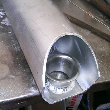
The plenum size was reduced already with the addition of the velocity stack plate, but it is still too large. The runners are now equal length and even spaced. Typical turbo builds will taper the plenum down toward the end to prevent starvation of the last port. This particular manifold will be fitted to a naturally aspirated engine which will not see the starvation issue associated, but I can't completely cut cylinder #1 off. The answer is a clever 3 angle reduction to bring the volume down and add a little deflection for any ram air effects.
The best way to cut a three angle end cap can be demonstrated up in 4 simple steps:
Cut it
Tape it
Transfer it
Weld it
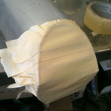
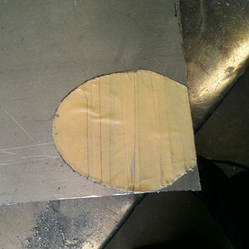
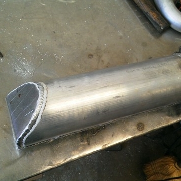
This is a fantastic method for creating cut templates for virtually any complex shape. Once it was all welded up, the rest of the plenum could be complete. All we needed now was a MAP bung, port block, and a throttle cable mount. The MAP bung was a transfer from a stock manifold. There was no way to ensure there would be the correct function and fitment without using a machine. Both port block and throttle cable mount were cut with a cut-off wheel and drilled by hand.


The Flange
Banging out and forming velocity stacks entirely by hand was one very challenging task. With a bit of work, I found the solutions, and the stacks were almost perfect. However, I now have a similar challenge I need to figure out in order to finish this project. The catch in this build was very simply stated: bare hands. No stationary machines are allowed under any circumstances. The challenge of the flange brought up one simple question:
How do I cut an oval hole with only hand tools?
I had to think "simplicity" for this one. An oval is essentially two round circles set at a specific distance apart. That is simple enough since I can easily cut two round holes and chase the area between out with a file. The injector port is also a round shape which can be cut with the hole saw.
The first step was to measure the mounting holes where the flange meets the head and transfer the measurements on to a 1/2" piece of 6061 aluminum. I could then bolt the manifold to the plate in order to trace out the pattern I needed to cut.
With the rough pattern on the plate, I could carefully measure out the locations for all the holes I need to cut. Each hole will match a radius section of the flange. Simply put, all I need to do in order to get this shape cut out by hand is match the radius in every location, and cut the rest with a cut-off wheel. This will give me the basic shape.


The ports were a little tricky. After some very careful measuring, I determined the radius of the port size and grabbed my hole saw. I started with the injector ports because they are the smallest, and will not remove too much metal to the point where I will not be able to pilot the two holes for the ports.
Cutting the ports out was tricky since the pilot was at the same point of the opposite port edge of the hole. The only way to get these holes cut was to cut into each hole about an 1/8 inch at a time. By the time one slug was cut, there was enough material already cut out of the other side to not need a pilot. After all the holes were cut out, a fie was used to knock down the center between each radius.


Consistency is key to manifold design and look. It wasn't necessary to cut all the ridges out of this flange, but it did make it look a lot better. To maintain consistency, I piloted each hole before chasing it out with a larger drill. This kept the radius of each ridge consistent. After all 34 holes were drilled into this flange plate, the cut-off wheel was used to cut to shape.


The Runners
The plenum, flange, and now runners can finally be welded together to make one intake manifold. To play safety on this one, I only tacked it so I can take it off of the jig and inspect it for correct alignment and fit. Once it was verified, the jig was destroyed.


The head side of the flange needs to have a near perfect surface since the intake manifold gasket is a metal type. I also wanted to make sure the manifold was a strong as possible when installed. The solution to both of these requirements is welding the inside of the runner to the flange. If you look carefully in the pic, you'll see two runners (not welded) are cut back far enough to allow a high build weld. The purpose of the high build weld is to allow me to grind away the weld for a smooth surface, but not take away from the integrity of the weld holding the two pieces together.


Injector Bungs
Two hurdles at this point have been solved. It's time for number 3:
How do I machine four injector bungs without a machine?
I had to get a little clever with this one. I knew I could have purchased four machined injector bungs for this build, but I could have also purchased a pre-made throttle body flange, head flange, an extruded plenum, and some spun velocity stacks. I really didn't see the point in purchasing just one section (other than the mandrel bends). I didn't feel that pre-made components would really demonstrate my ability to hand build a sheet metal intake manifold.
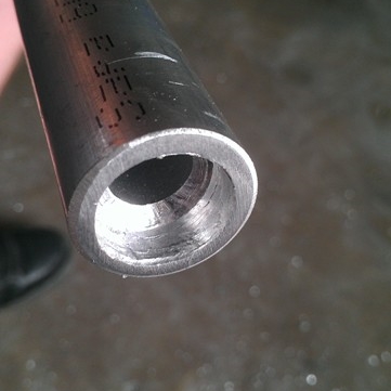
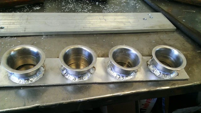
After some digging around in my remnants metal, I found some tubing that would make the perfect injector bungs. It was 1" OD x 0.25" wall, 6061 aluminum. Perfect! The 0.5" inside diameter of the tube is perfect for the spray tip body to pass though, and I can bore enough away for the injector base seals to seat correctly. Since the material is a tube, and not bar, I can use the inside diameter as a pilot while I carefully hand bore it with my drill.


I started by boring the inside of the bung where it opens up into the port. Boring allows the spray pattern to to evenly mist into the port. Keeping the 0.5" bore mighty interfere with the spray and cause dripping. The runners mate up to the flange at 90 degrees, so two wedge cuts were made with a cut-off wheel on my grinder to set the correct bung angle.


Once the bung was cut to length, the base seal bore was made using the drill. It only took a few minutes to lay down the outer welds, but the inner welds were a bit more difficult. While they were only filler welds, the space to work in is very tight for a weld torch and welding rod. It was kind of like trying to lay down a weld inside of a 3/4" tube. After some inside filler was laid down, the inside of the port and face of the flange was shaped and smoothed with the file and some emery cloth.
Full Assembly
I had to take a moment and check out what the manifold looked like in the sun for a few minutes before I finished the fuel rail mount.


Fuel Rail Mount
There are some things in this world that I will take on without the use of machinery, and there are others I will not. I had to machine a custom fuel rail to fit this manifold which required my mill and drill press. Since the fuel rail was not hand built, it will be left out of this build blog. However, the fuel rail mount was made entirely by hand. It only took a few cuts will the hole saw to match the radius of the runners followed by a few holes for the mount.


Complete hand fabrication has proven to be very challenging, but the hard part is definitely over with! Completing a project like an intake with nothing but my bare hands has been a great challenge and has assured me that my skills are still in tact for at least another year of fabrication.
Help fund future episodes of The Fabricator Series with your Donation and receive exclusive SnapChat access! Even the smallest donations go a long way.
Be sure to like, follow, and subscribe to all the social media pages for the latest updates!
So what do you think? Have any questions?
Tell me about it in the comments below of email The Fabricator.
Likes, comments, and shares appreciated by all!


Purge Blocks actually serve more than one purpose. Do you know what they do?